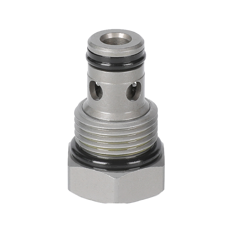
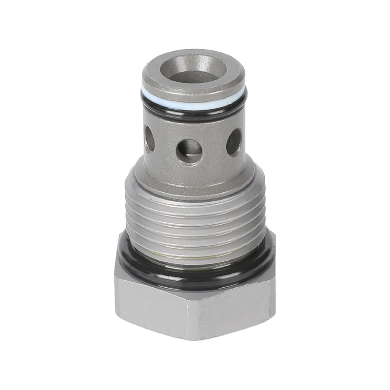
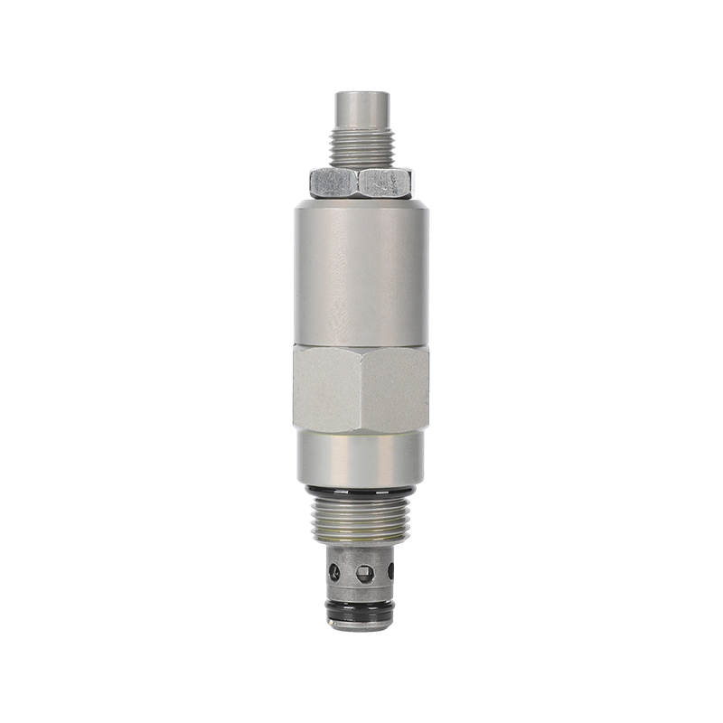
Flow control valves play a vital role in hydraulic, pneumatic and various industrial automation systems. They ensure system efficiency, stability and safety by regulating the flow rate of media (such as liquids or gases). The root cause of many system operation abnormalities comes from improper installation or calibration errors of flow control valves.
1. What Does Proper Installation Mean?
Proper installation is not just about “putting the valve on”, it involves several key factors:
Correct direction: Most flow control valves have flow direction indicators (arrows), and you must ensure that the valve is in the same direction as the medium. Reverse installation will result in limited flow or even damage to the internal structure.
Stable installation position: The valve should be installed in a vibration-free and firmly supported position to avoid loose valve body or seal failure due to shaking or stress during system operation.
Clean installation environment: Before installation, you must ensure that the inside of the pipeline is clean and free of impurities. Debris and rust particles may damage the valve core, causing jamming or leakage.
Compliance with connection standards: Standard flanges, sealing gaskets or threaded accessories should be used to avoid leakage or pressure loss due to mismatch.
2. Key Signs of Improper Installation
The following phenomena usually indicate that there may be installation problems with the flow control valve:
Unstable flow: During system operation, the flow is sometimes large and sometimes small, which is difficult to control.
Abnormal sound or vibration: The valve or pipeline makes a whistling or vibrating sound, which may be caused by internal cavitation or excessive pressure difference.
System leakage: Leakage at the joint or the valve body itself indicates a loose connection or poor sealing.
Slow valve response: The system responds slowly after adjusting the valve, indicating that the signal has not been transmitted in time or the valve core is stuck.
3. Understanding the meaning of valve calibration (Understanding Valve Calibration)
Calibration is a key step to ensure that the valve operates as expected. Common meanings include:
Set the flow corresponding to the opening angle: For example, turning the adjustment handle to 30%, does it really correspond to 30% of the maximum flow? This requires calibration.
Flow-pressure response consistency: The flow control of the system should remain consistent or change predictably under different pressures.
Compensation error: Different operating conditions (temperature, viscosity, etc.) may affect valve performance, which can be compensated through calibration.
The valve may have basic settings when it leaves the factory, but in actual use, it still needs to be calibrated again according to the system characteristics.
4. How to Calibrate a Flow Control Valve
The steps are as follows:
Prepare tools: prepare basic tools such as pressure gauges, digital flow meters, and torque wrenches.
Set the initial state: turn off the system or adjust to a low pressure state to ensure safety.
Adjust the valve step by step: adjust the amplitude by less than 10% each time, and record the corresponding flow or system performance.
Record data and create a table: create a comparison table of flow vs. valve opening.
Repeated verification: repeat the test under different pressure conditions of the system to ensure consistency.
Lock the setting after completion: some valves have locking screws, which must be fixed after adjustment.
Notes:
Avoid debugging under high temperature or high pressure.
For automatic control systems, synchronize the calibration of control signal outputs (such as 4–20mA or 0–10V, etc.).
5. Recommended Tools and Best Practices
To ensure efficient calibration and stable operation, the following practices are recommended:
Use high-precision instruments: such as electronic flow meters and digital pressure transmitters.
Regular maintenance plan: It is recommended to check and fine-tune the valve every 3 to 6 months.
Clear valve labeling: Mark the calibration date, responsible person, and scope of use for easy tracking.
Avoid human error adjustment: Install anti-misoperation devices or set permission control on key valves.
6. When to Seek Expert Help
It is recommended to contact professional technicians or manufacturers in the following situations:
Complex system or multi-variable control: such as PLC control, multi-loop flow management.
Abnormal response curve: The system responds abnormally, nonlinearly or lags after adjustment.
Frequent error alarm: The system frequently prompts "abnormal flow" or "pressure deviates from the set value".
Replace system components: If the pump or actuator is replaced, the valve matching should be re-evaluated.

 English
 русский
 ++86-0575-87669088


